Quick Start:
Before you get started:
Not every project is a good candidate to use Revit for HVAC loads. The best indicator of success is the architect’s use of rooms. If the architect is using rooms, it means the architect is defining the building envelope well enough to contain rooms (and therefore spaces). So, if the architect has rooms placed in every space that you need to run loads on, you are ready to try the Ripple HVAC Loads Toolkit.
We do not suggest working on a “live” BIM360 architectural model. Download a static copy of the current architectural model and link that in. As architects delete and redraw space bounding elements your spaces will disappear and reappear. This is very frustrating when it happens in real time.
Project Set Up:
- Link in the architectural model and set it as room bounding.
- Acquire Coordinates from the architect’s model and ensure building location and rotation are accurate.
- Align Levels to the architect’s model.
- Link in the electrical and/or lighting model as necessary.
- Copy monitor in the “light fixtures” category and the “electrical fixtures” category.
- Link in the furniture model as necessary.
The Toolkit (HVAC Loads Tab):
- Run the “Set Recommended Settings” button. Check that the ground Level is correct (Analyze Tab->Energy Settings->Ground Plane). Anything under the ground level will be assumed to have ground contact and no contact with the air or solar loads.
- Run the “Space Placement” button. This function will place a space in all rooms from all linked models and copy over room name and number to the space. It will raise the space height up to the highest ceiling, floor, or roof above the space and place a plenum space as necessary. Spaces should now encompass the entire volume of the conditioned building. Because they fill up the entire volume, they now contain the essential data about all of the bounding elements and can be used to calculate loads. See the images below, the first image contains spaces placed using the built-in Revit space placer, noticed how much roof and wall area is missing as opposed to the automatically placed spaces in the second image. Use color fill legends and elevation views to ensure that spaces were able to be placed and enclosed.
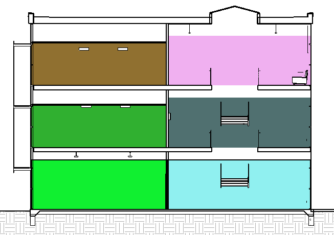
Figure 1. Spaces placed manually, notice plenum spaces aren’t placed, spaces don’t reach the ceiling so many lights aren’t in the space. |
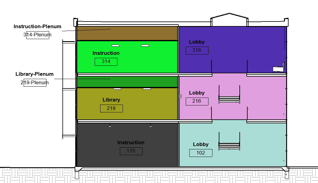
Figure 2. Spaces automatically placed with Ripple Loads Toolkit |
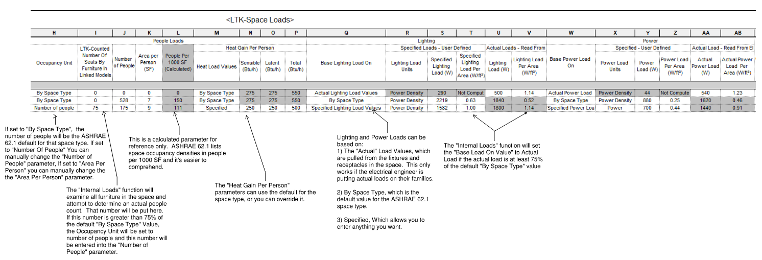
- Run the “Occupancy Category” button. This function will look at the space name, area, and other parameters and guess what the ASHRAE 62.1 category should be. Check the “Space Type” parameter in the “LTK-Space Loads” schedule to assign spaces that were unable to be assigned or assigned incorrectly. Now would also be a good time to make any modifications to the Space Temperature Setpoints in the schedule.
- Run the “Internal Loads” button. This button will compare the actual internal load values with what the space type expects and use the most likely value.
- Lighting and Power Loads: The Space Type contains default lighting and power load data about the space, the model contains actual load data, read from the actual “light fixture” category and the “electrical fixtures” category that are in the space (which is why you copy monitored those categories into your model). Because you may need to run loads before the electrical engineer is done placing lights and receptacles, you may want to use the space default. If the electrical engineer has already placed his lights and they are contain realistic loads, you may want to use the “Actual” value. You may also want to override to your own value. You can take any path, but the “Internal Loads Assistant” looks to see if the electrical data is at least 75% of what was expected of the Space Type, and if it is, it sets the “Base Load On” parameter to “Actual”. If you would like to input your own load in for these values, change the respective “Base Load On” parameter to “Specified Load Values” and then you can type in whatever value would like.
- People: by default, Revit has no “Actual” People count for spaces. “Internal Loads Assistant” attempts to count the amount of people in the space by examining all of the furniture in the space and adding up all of the seats to get a people count, just like with power and lighting, if that count is at least 75% of what was expected it will set the “Occupancy Unit” to “Number of People” and insert the counted number of people. Regardless, the number will be added to the “LTK-Counted Number Of Seats By Furniture In Linked Models” Parameter.
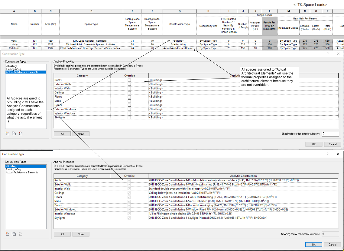
- External Loads: There are two ways that Revit passes the thermal properties of building elements into gbXML or its internal loads tool. One way is to override the thermal properties of the element category and the other way is to use the actual thermal properties defined in the element. Because architects are generally not good at defining thermal properties, we highly recommend that you override everywhere that you can and then only checking and fixing the architect’s elements as necessary. When overriding architectural elements, you can only pick one set of thermal properties for each category (roof, wall, ect.) that overrides every element of that category in the space. This only becomes a problem when a space has two different construction types. For instance, two different windows types that have different enough SHGCs for it to make a noticeable impact on the loads in a single space. In this situation, you can correct the architectural elements but by only focusing on that space.
- If the project is early enough in design that the architect does not have construction details and window selections yet, you can run the “Set Code Minimum Construction Types”. This sets your <building> default to the IECC code minimum thermal properties for the project zone (United States Only). This can be modified by going to Analyze Tab -> Energy Settings -> Advanced Options -> Schematic Types.
- You can create other schematic types and assign them to spaces by clicking on the edit button next to <building>. The default construction types that come with Revit out of the box can be viewed here: https://download.autodesk.com/us/revit_mep_2016/constructions-revised.pdf. The Ripple HVAC Loads toolkit comes with IECC defaults, whose properties are listed in the construction name, which are derived from the International Energy Conservation Code. If you would like to add your own construction type you can do that by clicking the “Add Construction Type” Function.
-
- Hopefully, you have been able to override everything in the building. If not, you can view what elements are still not overridden by clicking on the “Architectural Element Finder”. This function will find all of the elements that are not overridden and display them and their thermal properties. You can then go into the architectural model and correct only these elements. If you would like to view ALL elements, regardless of if they are overridden or not, change the radio button to “Find All Elements That Are Bounding Spaces”
- You are now ready to either export a gbXML file or use the built in Revit Loads engine to calculate heating and cooling loads.
- To run loads using the Revit built in Loads engine, go to Analyze -> Heating and Cooling Loads, then click calculate, recommended settings are already set from the “Set Recommended Settings”.
- To export a gbXML file, go to a 3d view->File->Export->gbXML. This file will contain all of the data you just collected and then can be imported into another Loads engine (Trane Trace, Carrier HAP, IESVE, ect.)
- If you used the Revit built in loads engine your Calculated Cooling Load and Calculated Heating Load parameter for each space will update. The loads engine will also populate your Specified Supply Airflow Parameter. But for a variety of reasons, this airflow parameter will be incorrect and not rounded. You can look at the LTK-Space Airflows schedule to calculate an accurate CFM. Set your Cooling Mode Supply Air Temperature (protip: you can select all spaces in the schedule, then click your default 3d view, and then change the parameter for all spaces selected in the properties window) parameter and your Override Supply Airflow will be calculated using Override Supply Airflow = Design Sensible Cooling Load / (1.08*(Cooling Mode Space Temperature Setpoint – Cooling Mode Supply Air Temperature). You can round and copy this number to the Specified Supply Airflow parameter by using the “Round and Assign Override CFM” function. Click on the button and it will pop up a dialog that will allow you to round the CFM to the nearest integer you would like. It will also set a minimum CFM so that low load spaces don’t end up with something un- balanceable, like 15 CFM.
- The software is set up to learn your preferences. So, if it guesses a space type wrong, and you have to correct it, or if you specify lighting load densities that are different than the default space types, the software will learn that and get more accurate on every release. Our goal is, that after a few projects, you will be comfortable with the defaults and if you have good and consistent architects, you will be able to calculate Heating and Cooling Loads at the click of a button. This is what the “Shoot the Moon” function does. It will run all of functions at once, including running loads. Hopefully soon you can click this button, grab a coffee, and come back to loads, CFMs, and start designing the project!
- Finally
- The built in Revit loads engine does not handle humidity calculations well. There is no input for additional humidity gain, so the only humidity considered is from the latent heat gain of people, which is unacceptable for spaces like natatoriums. The built-in loads engine also applies a radiant time series delay function to sensible loads, but not latent loads. So it assumes the latent loads are directly applied instantaneously, while the sensible loads have to heat up the thermal mass of the space before being applied. This drives the space sensible heat ratio way up and makes all spaces think they are humidity driven. In reality building materials absorb and release humidity and there should be delay function on the latent heat to. Revit also doesn’t understand the various control strategies for humidity control and how those will affect airflow. Therefore, we suggest performing humidity calculations separately as needed.
- HVAC zones in Revit are fundamentally broken. There’s no clear direction on what the zone is supposed to be. Is it a terminal unit zone? An AHU zone? A ventilation zone? Who knows, but the zones contain data that would apply to all of these zones types. For this reason we need to totally disregard zones, when you see zones in the loads report, disregard them and look at spaces only. The Ripple HVAC Loads Toolkit will automatically keep 1 zone synced with 1 space and keep the space temperature setpoints synced, because the internal loads engine uses the zone temperature. This will happen in the background, so disregard zones.
- Because zones are fundamentally broken, The built in “Plenum” parameter is also broken. Don’t use this. When ceilings are room bounding and plenums are placed, that load will be broken out separately. You can use it to calculate the return air temperature as you desire.
- ASHRAE 62.1 ventilation calculations are a complex beast that are beyond the scope of this toolkit. But since we already have collected a lot of the essential data (space type, area, and people counts) we should allow that data to ripple into your vent calcs. The HVAC loads toolkit provides the “LTK-Space Ventilation Estimate” as a starting point. You can manually insert your Ventilation System Number to group the spaces into ventilation zones. Then you will need enter your Air Distribution Effectiveness and manually calculate and enter your System Ventilation Effectiveness. See ASHRAE 62.1 for more details.
Deep Dive:
Coming soon….