Paper originally published in the ASHRAE Journal Here: https://www.nxtbook.com/nxtbooks/ashrae/ashraejournal_OKRFGH/index.php#/p/50
Practical Diffuser Selection and Layout Procedure
The selection and layout of diffusers to maximize occupant thermal comfort can be a complicated and time-consuming task. Given the sheer quantity of diffusers that must be selected and laid out on every project, developing a streamlined and consistent process can help firms remain profitable in a competitive environment. This paper intends to describe a practical selection and layout procedure that provides occupant comfort, minimizes construction cost, and can be applied to most spaces quickly and effectively.
Constraints:
No single procedure could encapsulate the engineering design required to adequately distribute air in any space that an architect can envision. There will always be edge cases and limitations. As such, we will work with the following constraints and assumptions:
The Characteristic Length, L:
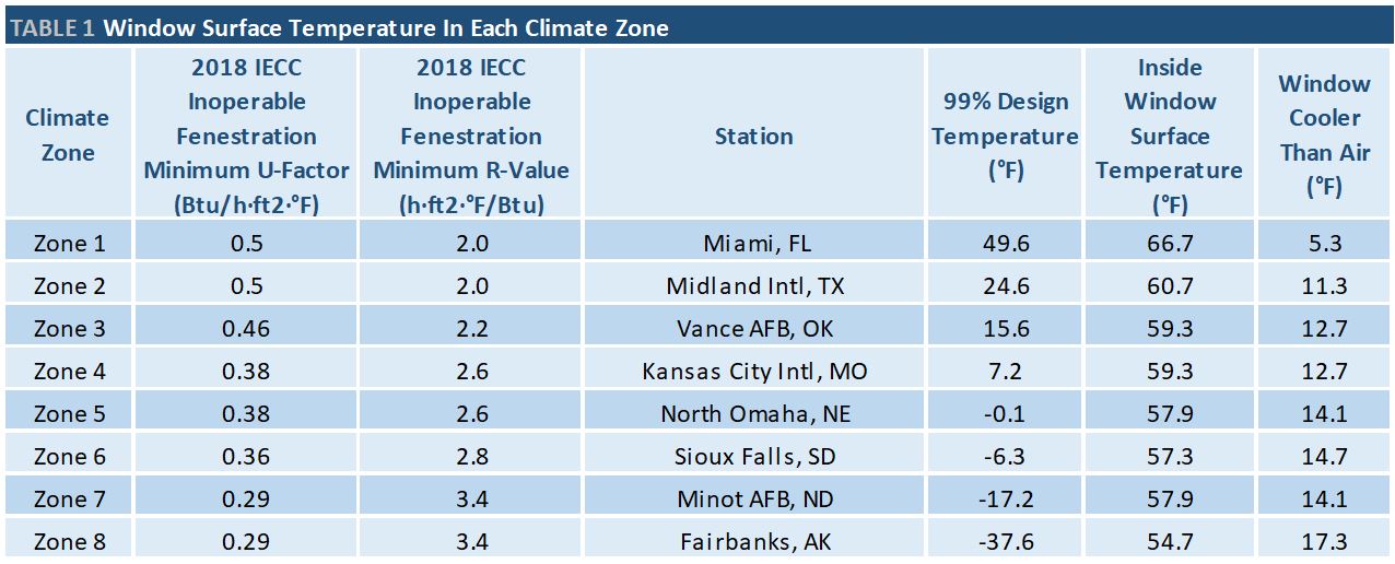
The characteristic length is defined by ASHRAE Applications chapter 57 for perforated and louvered ceiling diffusers as the “Distance to wall or midplane between outlets”2. It is a single number for the entire space, so an effort must be made to keep all diffusers in a space equidistant from walls and other outlets. In order to accomplish this let’s look at a few examples. First, a square 20’x20’ space with one diffuser as shown in Figure 1A. If the diffuser is placed directly in the center of the space, the space has a characteristic length of 10’. If the characteristic length needs to be decreased, the diffusers should be placed in a 2×2 grid as shown in figure 1B.
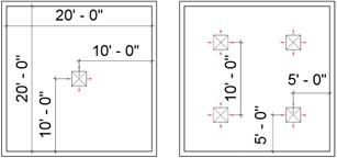
Figure 1A: L= 10′ Figure 1B: L = 5′
With a non-square 20’x40’ rectangular space as shown in Figure 2, a single diffuser will not give a consistent characteristic length. The characteristic length in the direction of the 40’ wall is 20’, while the characteristic length in the direction of the 20’ wall is 10’. This deviation in the characteristic length has real-world implications. Depending on the throw of the selected diffuser air may crash against the 40’ wall and leave occupants along the 20’ wall with stagnant air. If a 1×2 grid of diffusers is utilized, as shown in Figure 3, the characteristic length becomes a consistent 10’. If the characteristic length needs decreased, the grid must increase to 2×4, as depicted in Figure 4. A mathematical definition of this pattern would be to create a grid of ATW x ATW * SR, where SR is the aspect ratio of the space and ATW is the grid count in the width (shorter) dimension, which can be increased in order to decrease the characteristic length.
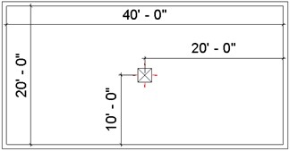
Figure 2: L = 10’ and 20’.
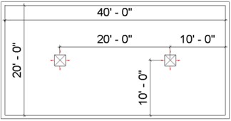
Figure 3: L = 10’.
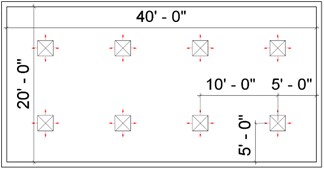
Figure 4: L = 5’.
In this 20’x40’ space, the number of diffusers increased from 2 diffusers to 8 diffusers. This is a significant construction cost increase because in addition to the diffuser cost, additional flex duct, runouts, dampers, and taps are required.
While spaces come in various aspect ratios, diffusers can only be placed in discrete grids, i.e., 1×2, 2×4. Therefore, we must accept that characteristic lengths may deviate. For instance, consider a 20’x25’ space (Space Aspect Ratio, SR, =1.25) which would require 20 diffusers in a 4×5 grid (Diffuser Aspect Ratio, ATR=1.25) to achieve a consistent characteristic length of 2’ 6”. Figure 5 demonstrates how impractical this is. In addition to the cost of the diffusers, the design does not allow space for other ceiling devices such as lights, sprinkler heads, or occupancy sensors.
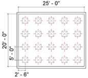
Figure 5: 4×5 diffuser pattern.
A 1×1 or 1×2 grid is much more reasonable for this space at the cost of having the characteristic length of the space slightly deviate (10’ vs 12’6” in the case of the 1×1 grid, and 6’3” vs 10’ in the case of a 1×2 grid, see Figure 6.
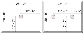
Figure 6: 1×1 and 1×2 diffuser pattern.
Because the characteristic lengths will vary slightly from diffuser to diffuser regardless, the constraint of keeping a perfectly consistent characteristic length can be relaxed and the ATW x ATW * SR layout grid can be improved by incrementally adding diffuser counts in the longer dimension using the following pseudocode algorithm:
SR = SL / SW
ATW = 1
ATL = ATW * [SR]
ATR = ATL / ATW
Loop:
If |ATR – SR| <= 0.5
ATL = ATL + 1
ATR = ATL / ATW
Else If |ATR – SR| > 0.5
ATW = ATW + 1
ATL = ATW * [RS]
ATR = ATL / ATW
Until: desired diffuser count, ATW *ATL is reached
Where SR is the space aspect ratio, calculated by dividing the space length, SL, by the space width, SW, in this example it is assumed that SL is the larger dimension. ATR is the diffuser aspect ratio, calculated by dividing the diffuser count in the larger dimension, ATL, by ATW, which is the diffuser count along the shorter dimension. To ensure the diffuser grid follows the space shape as close as possible, initially and every time we add a diffuser in the shorter dimension, we multiply the grid count in the shorter dimension, ATW, by the rounded space aspect ratio, [SR]. When the diffuser aspect ratio diverges too significantly from the space aspect ratio, as indicated by the absolute value of the difference of the two aspect ratios being greater than 0.5 (|ATR – SR| > 0.5), then a diffuser in the shorter dimension must be added and the grid reset to match the space aspect ratio as close as possible.
This algorithm allows the user to add diffusers in the smallest increment possible while maintaining the tightest characteristic length. In the case of our 20’ x 40’ space, the diffuser counts would progress from 2 -> 3 -> 4 -> 4 -> 6 ->8 as shown in Figure 7.
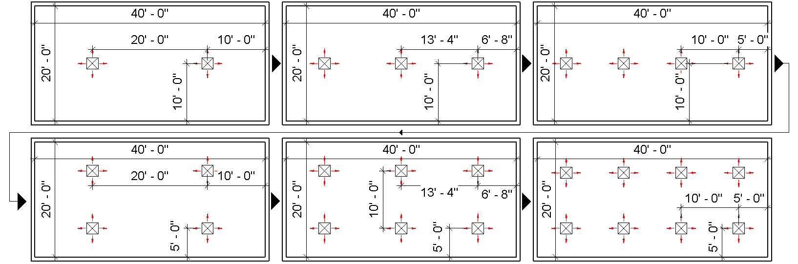
Figure 7: Air Terminal layout pattern progression for the first 6 loops.
Length to 50 fpm Terminal Velocity, T50:
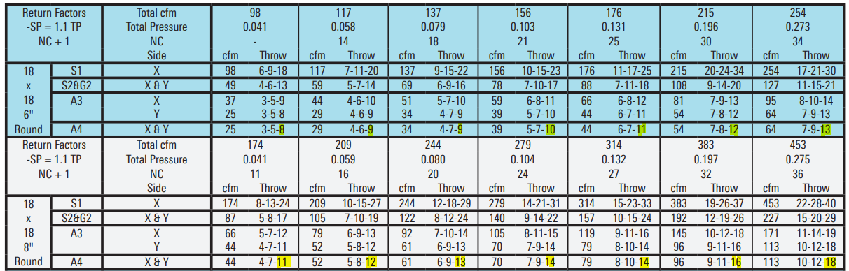
Regardless of what the ideal T50/L is, each diffuser is going to ideally “cover” some area for a given CFM based on the T50 throw of the diffuser. If the ideal T50/L is 1, then the area covered will be (T50*2 / 1)2, if the desired T50/L is 2, then the area covered is (T50*2 / 2)2. For an example from Figure 8, an 8” 4-way louvered face diffuser with 314 CFM of supply air would have a T50 throw of 14’ in all 4 directions, and with an ideal T50/L of 1, would cover a 28’x28’ area, or 784 s.f.
 .
.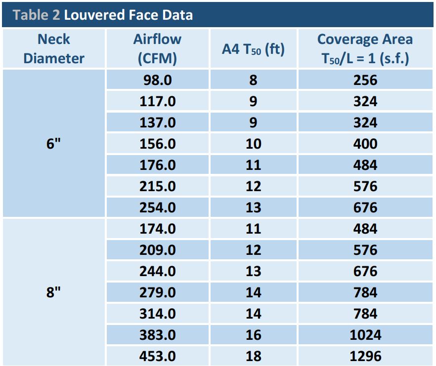
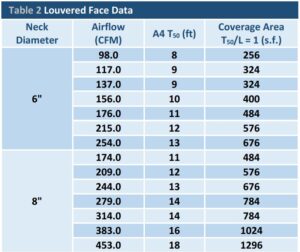
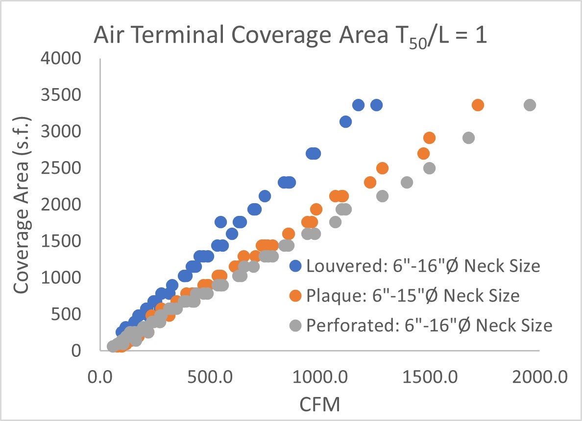
These areas are calculated for 6” and 8” in Table 2. If the coverage areas vs. the CFM across all neck sizes are plotted as shown in Figure 9, it is clear that the area “covered” by each diffuser is linear with the CFM applied. This holds true for many popular diffuser types, including radial plaque and perforated.
ad
Figure 9: Diffuser coverage area for popular models.
Because the coverage area decreases linearly with the CFM applied, even across multiple neck sizes, coverage area cannot be increased simply by adding more diffusers. If the diffuser count is increased from 1 to 4, the CFM available to assign each diffuser reduces by ¼ and the coverage area remains the same.
For example, assume 314 CFM is being delivered to a 20’x20’ space (0.785 CFM/s.f.), and a louvered face diffuser from Figure 8 with an ideal T50/L of 2 is used. If one 8” neck diffuser is placed in the center of the space, the characteristic length would be 10’ and the actual T50 would be 14, so the actual T50/L is 1.4 (14/10) which is only 70% (1.4/2) of the ideal 2. If the characteristic length is reduced to 5’ by placing four 6” neck diffusers, each diffuser would now only have 78.5 CFM and a 7’ throw. In this case, the actual T50/L is still 1.4 (7/5), and which is still 70% of the ideal 2, but now with more construction cost. Because the coverage area decreases linearly with the CFM applied, even across multiple neck sizes, this is true in all situations.
This demonstrates that with the given constraints, the actual T50/L is decided solely by the diffuser type and the airflow density (CFM/s.f.) of the space. With popular diffuser types and standard ranges of airflow densities at maximum flow, ideal T50/L ranges are typically met. It’s important to note, that while catalogue data is typically presented for isothermal conditions (i.e., supply air temperature equals room temperature), non-isothermal correction factors will only increase or decrease the slope of the coverage area vs. CFM lines, so the range of acceptable airflow densities will change in heating and cooling mode, but the conclusion is the same: adding more diffusers does not lead to better coverage.
As previously mentioned, with popular diffuser types and standard ranges of airflow densities at maximum flow, ideal T50/L ranges are typically met. However, at VAV minimum flow, the actual T50/L will typically be far below the ideal T50/L range. This is the situation that most engineers refer to as “dumping”, where there is not enough airflow coming out of the diffuser to cause adequate mixing and the air “dumps” onto the occupants, causing discomfort. While it may seem like “dumping” is a diffuser layout problem, it is a VAV minimum setpoint problem. Again, adding more diffusers does not alleviate the “dumping” problem because, for example, it is unclear if it is better to “dump” 40 CFM out of one 8” diffuser or 10 CFM out of four 6” diffusers.
To help accept the fact that the ideal T50/L will not be met at VAV minimum, consider a 2014 ASHRAE Research Project entitled “Thermal and Air Quality Acceptability in Buildings that Reduce Energy by Reducing Minimum Airflow from Overhead Diffusers” which showed that thermal comfort significantly improved when VAV minimums were reduced from 30% to 10% of maximum flow4, therefore the lower bound of the ideal T50/L ranges probably need to be reassessed.
Complex Spaces:
Complex spaces are a conglomerate of simple spaces. To address complex space, break them into simple rectangular subspaces and treat them separately.
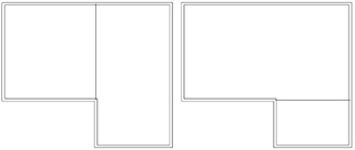
Because architects are concerned about sight lights, complex spaces should be decomposed in a manner that leaves the largest area intact. For instance, the L shape space in figure 10 could be decomposed with a vertical line shown in the left image, or a horizontal line shown in the right image. The right image would have the largest consistent diffuser grid pattern and the most aesthetically pleasing sight lines, so it is the logical choice.
 .
.Figure 10: 2 ways of decomposing a space.
As shown in the previous section, coverage area decreases linearly with CFM, if more CFM is assigned to one subspace to attempt to get better coverage for that subspace, the other subspaces will be under covered. Therefore, CFM should be simply assigned to each subspace in proportion to its area.
There are some layouts in which uneven CFM distribution would be desired, for example, a lab space with many hot plates in a nook or a space with uninsulated brick and single pane glass walls.
Procedure:
Now that the individual components of the procedure have been addressed, we can formulate a streamlined and consistent process:
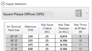
Figure 11: An example table of the maximum allowable CFM.
Characteristic Length section of this paper.
As pseudocode:
For Each Subspace SS, in Space S
CFMSS = CFMS * SSA / SA
SR = SL / SW
ATW = 1
ATL = ATW * [SR]
ATR = ATL / ATW
Loop:
If CFMSS / (ATW *ATL) < CFMMax
Break
If |RAT – Rs| <= 0.5
ATL = ATL + 1
Else If |ATR – SR| > 0.5
ATW = ATW + 1
ATL = ATW * [RS]
ATR = ATL / ATW
End
The algorithm works well for many spaces, however the isovel method of diffuser layout cannot be totally disregarded. In some cases, ceiling spaces can be very cluttered due to other ceiling devices such as lighting, smoke detectors, and sprinkler heads which may take precedence, so the diffusers get pushed from their ideal location closer to the perimeter or an adjacent diffuser. This may require users to map the isovels to ensure air isn’t crashing on a wall or adjacent airstream at too high of a velocity, which could cause uncomfortable drafts in the occupied zone.
These rules don’t work well for long thin spaces, such as corridors, which may have aspect ratios of 10+. In this scenario, placing 10 diffusers down a hallway may not be worth it, two way throw patterns should be installed instead.
Additional Diffuser Suggestions:
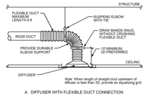
Figure 12: Straight duct requirement
Conclusion:
Most designers and engineers follow the procedure outlined in this paper quickly and instinctively when laying out diffusers for most spaces. However, it is important to document our knowledge for new entrants to the industry and so that tools can be built to automate the more repetitive tasks.
References: