Introduction:
Our goal with the Revit® HVAC Loads Toolkit is to allow you to calculate complete and accurate load calculations with a single click of a button. With that being said, not every project is a good candidate to use Revit for HVAC loads. The best indicator of success is the architect’s use of rooms. If the architect is using rooms, it means the architect is defining the building envelope well enough to contain rooms (and therefore spaces). So, if the architect has rooms placed in every space that you need to run loads on, you are ready to try the Ripple HVAC Loads Toolkit.
Project Set Up:
Most firm’s project setup process already includes most of these steps, but we would like to highlight why they are important.
- Link in the architectural model and set it as room bounding. The same elements that bound the architect’s Rooms, need to bound the mechanical Spaces. More Information.
- If there is a furniture model that is separate from the architectural model, link it in so that the “Set Internal Loads” function can count seats and estimate a person load.
- Acquire Coordinates from the architect’s model. This will set your location which is required to acquire weather data. It will also set your building orientation which the load engine needs. More Information.
- Ensure your location and orientation is correct and make any adjustments to the desired design temperatures and clearness number in Manage Tab -> Project Location Pane -> Location.
- Ensure you have levels that are aligned with the architect’s levels. Your Spaces will need to be bounded by the same elements as the architect’s Rooms and if the levels aren’t aligned, the bounding elements will not work properly.
- If your firm uses separate mechanical and electrical/lighting models, link in the electrical and/or lighting models and Copy/Monitor in the “light fixtures” category and the “electrical fixtures” category. This will allow you to pull the electrical data from the actual electric elements into your space load. The electrical load can be overridden if necessary, but it’s a good comparison.
The Toolkit (RippleHVAC Tab):
- The settings that effect the load calculations are scattered throughout a few different dialogs. In order to simplify project set up, we have made the “Set Recommended Settings” button. Click this button and the recommended settings will be applied to the project.
- The recommended settings can be viewed here.
- The hardest setting to estimate is the ground Level, so check that it is correct (Analyze Tab->Energy Settings->Ground Plane). Anything under the ground level will be assumed to have ground contact and no contact with the air or solar loads.
- Run the “Rooms to Spaces” button.
- This function will place a space in all rooms from all linked models and copy over room name and number to the space.
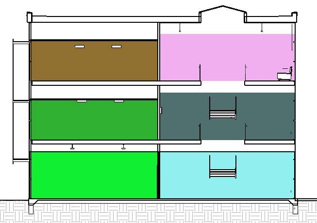
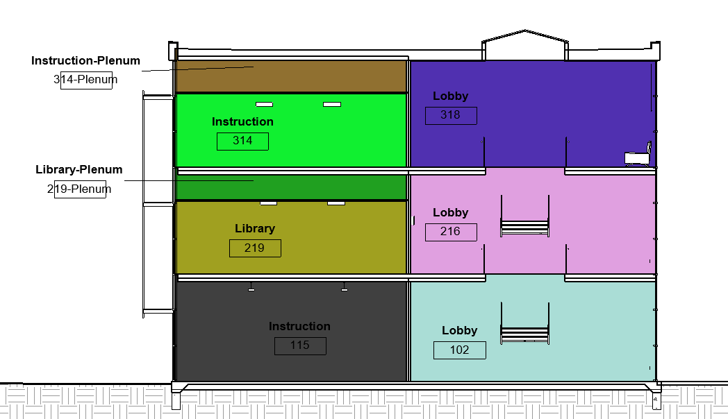
- It will raise the space height up to the highest ceiling, floor, or roof above the space and place a plenum space as necessary. Spaces should now encompass the entire volume of the conditioned building. Because they fill up the entire volume, they now contain the essential data about all of the bounding elements and can be used to calculate loads. See the images below, the first image contains spaces placed using the built-in Revit space placer, noticed how much roof and wall area is missing as opposed to the automatically placed spaces in the second image.
|
Figure 1. Spaces placed manually, notice plenum spaces aren’t placed, spaces don’t reach the ceiling so many lights aren’t in the space. |
Figure 2. Spaces automatically placed with Ripple Loads Toolkit |
-
- In addition to the spaces now encompassing the entire envelope, they will also contain the lights that are typically above the space, this helps with internal load calculations.
- This button will only copy over spaces where the architect had rooms, so you want to ensure that that any enclosed area with a height and a width over the “sliver space tolerance” setting (default value = 3’) has a space placed in it OR you need to increase the “sliver space tolerance”. When you’re setting the sliver space tolerance you should be thinking of what the smallest dimension in the building that is actually exposed to the exterior. For example, if you have a 3’ 1” outdoor alleyway that cuts into your building, you can set your sliver space tolerance to 3’ 0” so that the model doesn’t disregard the alleyway as an outdoor space, but still ignores all of the 3’ chases and voids around the building. If the sliver spaces aren’t accounted for, the load engine will assume that the sliver space is exterior. Typically, these internal walls will have not windows, so the impact on the load will be minimal. But it is good practice to review the space placement to ensure the entire building envelope is captured. Using color fill legends (Analyze Tab -> Color Fill Panel -> Color Fill Legend) is a good way to view the spaces in floor plan graphically.
- This button can be run multiple times throughout the projects as rooms are added or room names and numbers are updated. It will only add new spaces and update room names/numbers as necessary.
- Run the “Assign Occupancy Category” button.
- This function will attempt to assign an ASHRAE 62.1 occupancy category based on the room name and area.
- Review the “LTK-Space Loads” schedule and check the “Space Type” parameter to assign spaces that were unable to be assigned (space type is <building>) or assigned incorrectly.
- Review and modify the desired “Cooling Mode Space Temperature Setpoints” and “Heating Mode Space Temperature Setpoint” as necessary.
- Review the default internal loads (area per person, heat gain per person, lighting, and plug) for the space type selections. You can modify these default values for any space type in Manage Tab -> MEP Settings -> Building/Space Type Settings -> Select Space Type.
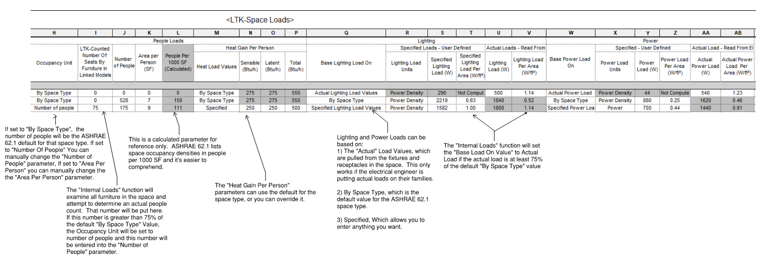
- Run the “Internal Loads” button. This button will compare the actual internal load values with what the space type default values and uses the most likely value.
- Lighting and Power Loads: The space type contains default lighting and power load data about the space, the model contains actual load data, read from the actual “light fixture” category and the “electrical fixtures” category that are in the space (which is why you copy monitored those categories into your model). Because you may need to run loads before the electrical engineer is finished placing lights and receptacles, you may want to use the space default. If the electrical engineer has already placed his lights and they contain realistic loads, you may want to use the “Actual” value. You may also want to override to your own value. You can take any path, but the “Internal Loads Assistant” looks to see if the actual electrical data is at least 75% of what was expected by the space type default, and if it is, it sets the “Base Load On” parameter to “Actual”. If you would like to input your own load in for these values, change the respective “Base Load On” parameter to “Specified Load Values” and then you can type in whatever value would like.
- People: by default, Revit has no “Actual” People count for spaces. “Internal Loads Assistant” attempts to count the amount of people in the space by examining all of the furniture in the space and adding up all of the seats to get a people count, just like with power and lighting, if that count is at least 75% of what was expected it will set the “Occupancy Unit” to “Number of People” and insert the counted number of people. Regardless, the number will be added to the “LTK-Counted Number Of Seats By Furniture In Linked Models” Parameter.
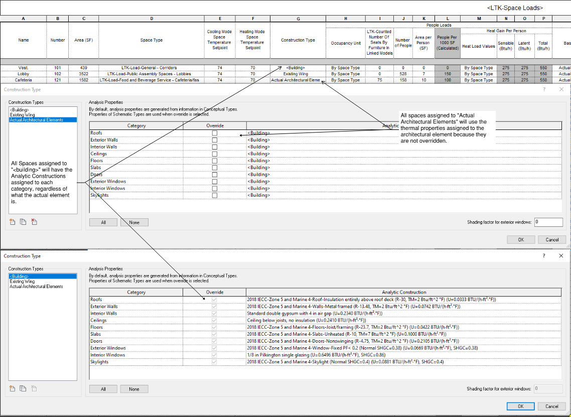
- External Loads: There are two ways that Revit passes the thermal properties of building elements into a gbXML or the internal loads tool. One way is to override the thermal properties of the element category and the other way is to use the actual thermal properties defined in the element. Because architects are generally not good at defining thermal properties, we highly recommend that you override everywhere that you can and then only check and fix the architect’s elements where absolutely necessary.
- With the proliferation of the adoption of the International Energy Code, the thermal properties of building assemblies are beginning to consolidate. A code minimum assembly has much better thermal performance than traditional assemblies and going much above code minimum only gives you quickly diminishing returns. For this reason, most architects are just meeting code minimum. This makes running loads much easier. If all of the assemblies in the project are going to be close to code minimum, we only need to simply override all of the thermal properties to code minimum. For this reason, the loads toolkit includes all of the code minimum construction types prebuilt for assignment. The “Set Code Minimum Construction Types” button sets your building default to the IECC code minimum thermal properties for the project zone (United States Only). The project zone and construction types can be changed by going to Analyze Tab -> Energy Settings -> Advanced Options -> Schematic Types.
- Thermal properties can also be overridden on a space-by-space basis. So, for example, if you have an addition to an existing building, and the addition will be code minimum but the existing building will be something less than that, you can create a new Construction Type, set the override thermal properties appropriately and then assign that to the Construction Type space parameter to all the spaces in the existing building.
-
- When overriding architectural elements, you are limited to the constructions found in your Constructions.xml file located on your computer at C:\Program Files\Autodesk\Revit 20xx\en-US\Constructions.xml. In addition to Revit default constructions located here, the loads toolkit includes 2018 IECC code minimum construction types from ASHRAE 90.1 appendix A. The Ripple Loads Toolkit includes a way to view this file and to add/delete materials, constructions, and windows. When you click on the Constructions Manager button a user interface will pop up that displays all of the materials, constructions, and windows.
- The materials contain an R-Value and may contain information that accounts for thermal mass. To add a new material, pick a unique name, an R-value, and include thickness, density, and specific heat if you would like to account for the thermal mass of the material. Finally, click add.
- The constructions (Interior/Exterior Walls, Roofs, Floors/Slabs, and Doors) are composed of a set of materials, these materials can be viewed in the library by expanding the construction. To add a new construction, pick a unique name and a list of materials that composes the construction. Check which type(s) of construction you would like to add this construction to. Finally, click add.
- The windows/skylights are defined by an R-Value, solar heat gain coefficients (SHGC) at different angles, and visible transmittance, see the Fenestration Chapter in the ASHRAE Fundamentals Handbook for more information. Enter these values, check the types, and hit Add.
- When overriding architectural elements, you can only pick one set of thermal properties for each category (roof, wall, ect.) which overrides every element of that category in the space. This only becomes a problem when a single space has two different construction types. If the thermal properties are close enough, it may be practical to pick the worse thermal properties and apply those to the whole space. This will give you slightly conservative load calculations but save you a lot of time. If the thermal properties are drastically different, you have to correct the actual architectural elements in the architectural model. If it is a single space with a single type that needs to be overridden, this may be easy to do manually, but as the spaces or types grow we need a tool to help us pinpoint the constructions that need to be corrected. This is what the “Architectural Element Finder” button is for.
- If you would like to pinpoint elements whose thermal properties will actively be used in load calculations, check the “Find Active Elements Only” button and hit “Find Elements”. The lists below will give you a list of materials, constructions, and openings that are not overridden and will need to have the correct thermal properties applied before accurate loads can be attained.
- Architects typically get the materials and dimensions of their constructions correct. This is what they use to show wall details, so it behooves them to do so. In these cases, it may just be a matter of correcting a few material thermal properties to get all of the constructions correct. If it’s an architect you work with frequently, or an in-house architect, you may want to offer to update their material thermal properties so that as they create new construction types, the thermal properties will automatically be applied. However, architect’s typically have libraries with thousands of materials, how do you know which ones matter? If you check the “Find All Elements” button and hit “Find Elements”, the list will return every element and it’s materials that is bounding a space, regardless of if it’s overridden or not. This give’s you a list of materials, constructions, and openings to correct.
- When overriding architectural elements, you are limited to the constructions found in your Constructions.xml file located on your computer at C:\Program Files\Autodesk\Revit 20xx\en-US\Constructions.xml. In addition to Revit default constructions located here, the loads toolkit includes 2018 IECC code minimum construction types from ASHRAE 90.1 appendix A. The Ripple Loads Toolkit includes a way to view this file and to add/delete materials, constructions, and windows. When you click on the Constructions Manager button a user interface will pop up that displays all of the materials, constructions, and windows.
- You are now ready to either export a gbXML file or use the built in Revit Loads engine to calculate heating and cooling loads. We highly suggest using the Revit built in loads engine, it has been shown to be accurate if the entire space envelope is encompassed. The Revit gbXML export works well, however the problem we have found is that all of the third-party engines do a poor job of importing gbXMLs, and since they don’t have APIs to automatically correct errors, you are stuck manually aligning the gbXML with the software standards.
- To run loads using the Revit built in Loads engine, go to Analyze -> Heating and Cooling Loads, then click calculate, recommended settings are already set from the “Set Recommended Settings” button.
- To export a gbXML file, go to a 3d view->File->Export->gbXML. This file will contain all of the data you just collected and then can be imported into another Loads engine (Trane Trace, Carrier HAP, IESVE, ect.)
- If you used the Revit built in loads engine your Calculated Cooling Load and Calculated Heating Load parameter for each space will update. The loads engine will also populate your Specified Supply Airflow Parameter. But for a variety of reasons, this airflow parameter will be incorrect and not rounded. You can look at the LTK-Space Airflows schedule to calculate an accurate CFM. Set your Cooling Mode Supply Air Temperature (protip: you can select all spaces in the schedule, then click your default 3d view, and then change the parameter for all spaces selected in the properties window) parameter and your Override Supply Airflow will be calculated using Override Supply Airflow = Design Sensible Cooling Load / (1.08*(Cooling Mode Space Temperature Setpoint – Cooling Mode Supply Air Temperature). You can round and copy this number to the Specified Supply Airflow parameter by using the “Round and Assign Override CFM” button. Click on the button and it will pop up a dialog that will allow you to round the CFM to the nearest integer you would like. It will also set a minimum CFM so that low load spaces don’t end up with something un- balanceable, like 15 CFM.
- Each button is designed to break up the process so that a person can review it at each step of the way. However, after a few runs when you are comfortable with the Space Type defaults and if you have good and consistent architects, you should be able to calculate load at a single click of the button. That is what the “1-Click Loads” button is for. This button essentially hits all the buttons at once: Placing full spaces, assigning occupancy categories, reviewing internal loads, setting code minimum construction types, running loads, and rounding and assigning supply air CFM all happens at once! We’d like to get you to a point where you can hit “1-Click Loads”, grab a coffee, and come back and start designing the projects with accurate CFMs assigned to every space.
Tips and Tricks:
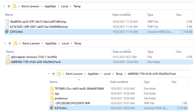
- Reviewing and Documenting Load Calculations: The “LTK-Space Loads” schedule is a nice overview of the loads and it can be exported to a .txt file (From the schedule view go to File -> Export -> Reports -> Schedule, pick the folder you would like and hit save, delimiter = tab). This text file can be copied and pasted into a spreadsheet that can be edited and saved for documentation. There is also a Loads Report that can be viewed from the Project Browser -> Loads Report, this report can be accessed outside of Revit in the temp folder at C:\Users\username\AppData\Local\Temp\ (this folder can be reached by typing “%temp%” into windows explorer). Depending on which version of Revit you are using, the report file will either be in the root directory or inside a subfolder with a GUID (e.g. “4df8f368-71f0-41d5-a33f-85e294c91ecb”). The loads report will be a .htm file with a name like “ILRxx”, you can open it with your favorite browser and verify the date. This file can be copied to your project location for documentation purposes and can be copied and pasted into a spreadsheet. When reviewing the loads report, remember to disregard Zone Summary, which will contain unnecessary and unreliable information about Psychometrics and hypothetical equipment selections. The partition load includes load from adjacent spaces with different space temperature setpoints, including plenum loads.
- Space Types: The Ripple HVAC Loads Toolkit comes with all ASHRAE 62.1 space types built in, the ventilation values are based on ASHRAE 62.1-2016 and the default lighting and plug load densities are based on IECC code maximums for similar space types. All schedules for loads are set to be on 24/7. The loads engine will apply only fraction of internal loads depending on the schedule, so if peak exterior load occurs at 10 AM, but you only have the occupancy at 70% at 10 AM, the full load will be exterior load + 70% of the internal load. We prefer to assume the all the lights are on during the peak exterior load. You can change the space type settings to match your preferences as necessary in Manage Tab -> MEP Settings -> Building/Space Type Settings -> Select Space Type. The only thing you shouldn’t change is the space type name.
- Humidity Calculations: The built in Revit loads engine does not handle humidity calculations well. There is no input for additional humidity gain, so the only humidity considered is from the latent heat gain of people, which is unacceptable for spaces like natatoriums. The built-in loads engine also applies a radiant time series delay function to sensible loads, but not latent loads, it assumes the latent loads are directly applied instantaneously, while the sensible loads have to heat up the thermal mass of the space before being applied. This drives the space sensible heat ratio way up and makes all spaces think they are humidity driven. In reality building materials absorb and release humidity and there should be delay function on the latent heat too. Revit also doesn’t understand the various control strategies for humidity control and how those will affect airflow. Therefore, we suggest performing humidity calculations separately on spaces where humidity control is a concern, such as natatoriums and laundry rooms.
- Revit HVAC Zones: The HVAC Zones category in Revit has some issues. There’s no clear direction on what the HVAC Zone is supposed to be. Is it a terminal unit zone? An AHU zone? A ventilation zone? The HVAC Zones contain data behavior that would apply to all of these zone types. For instance, when calculating loads, any space on that zone that is marked plenum (yes/no “Plenum” Parameter is checked) will not have a load calculated and reported. Instead, it will attempt to apply that load to the return air of the AHU (or whatever system type you have selected). This sounds okay in theory, but the HVAC Zone also contains the temperature setpoints, so unless your whole AHU zone is going have the same temperature setpoint, you can’t use it as an AHU zone. For this reason, we need to totally disregard zones, when you see zones in the loads report, disregard them and look at spaces only. The Ripple HVAC Loads Toolkit will automatically keep 1 zone synced with 1 space and keep the space temperature setpoints synced, because the internal loads engine uses the zone temperature. This will happen in the background, so disregard zones. If you have been using HVAC Zones with Color Fill Legends for visualization, we suggest creating a different Space text parameter such as “AHU Zone” or “Terminal Unit Zone” which can accomplish the same task and be more descriptive of what you are trying to visualize.
- Plenums: There are two methods engineers typically use to address plenums, the first method is to calculate a separate load for a plenum and apply that load to the return air. This leads to slightly lower airflow with an elevated return air temperature. The second method is to calculate a single load for the space and plenum combined, this leads to a slightly higher airflow to space, but a lower coil return air temperature. If you would like to calculate loads using the second method (combined space + plenum) you need to set all of the ceilings in the space to not be room bounding before you run the “Rooms to Spaces” button. The easiest way to do this is to go into the architectural model, make a ceiling schedule to show all ceilings, select all the ceilings in the schedule, go to your default 3d view, and then uncheck the “Room Bounding” parameter. Now the “Rooms to Spaces” button will increase the space height to the floor above or roof, instead of the ceiling. If you would like to calculate loads using the first method, make sure the ceilings are set to room bounding (architect’s typically have this set by default). The “Rooms To Spaces” button will automatically place plenums and plenum levels as necessary and calculate a separate load for them. As described in the previous section on HVAC Zones, the OOTB Plenum Yes/No Parameter causes a load to not be calculated for that space, so don’t use it. By default, the lighting plenum contribution is set to 0% for all Loads Toolkit space types.
- Work from a Stagnant Architectural Model: If you need to make many changes to the architectural model, such as edit material thermal properties, modify Room separation lines, and change the bounding of all of the ceilings, but the architect is hesitant to let you make that many changes, feel free to make a copy of their model, make the required modifications, and work in the stagnant copy to get loads ran.
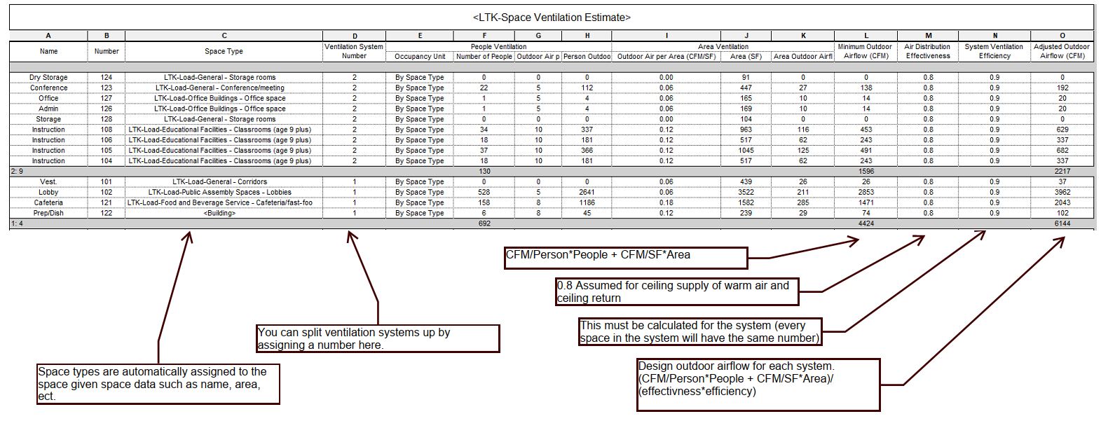
- Ventilation Calculations: ASHRAE 62.1 ventilation calculations are currently beyond the scope of this toolkit. But since we already have collected a lot of the essential data (space type, area, and people counts) we should allow that data to ripple into your vent calcs. The HVAC loads toolkit provides the “LTK-Space Ventilation Estimate” as a starting point. You can manually insert your Ventilation System Number to group the spaces into ventilation zones. Then you will need enter your Air Distribution Effectiveness and manually calculate and enter your System Ventilation Effectiveness. See ASHRAE 62.1 for more details.